How to wire a smart switch
Before we get into the details of smart switch wiring, let’s cover basic switch wiring for a regular (non-smart) switch. This knowledge will serve as a good base to build from for wiring a smart switch.
Home electrical wiring contains two wires – the black wire (hot) and the white wire (neutral). There is also a green wire for the ground. The ground wire is important for proper grounding, but not relevant to how a switch works.
A circuit is completed by the black wire carrying power to the device (like a light), and the white wire completing the circuit and returning to the circuit box. So, if you look at anything that is powered in your home, like a plug, light, dishwasher, etc., they all have black and white wires running to them. These are usually carried in a single bundle of wires wrapped in a white sheathing, such as Romex.
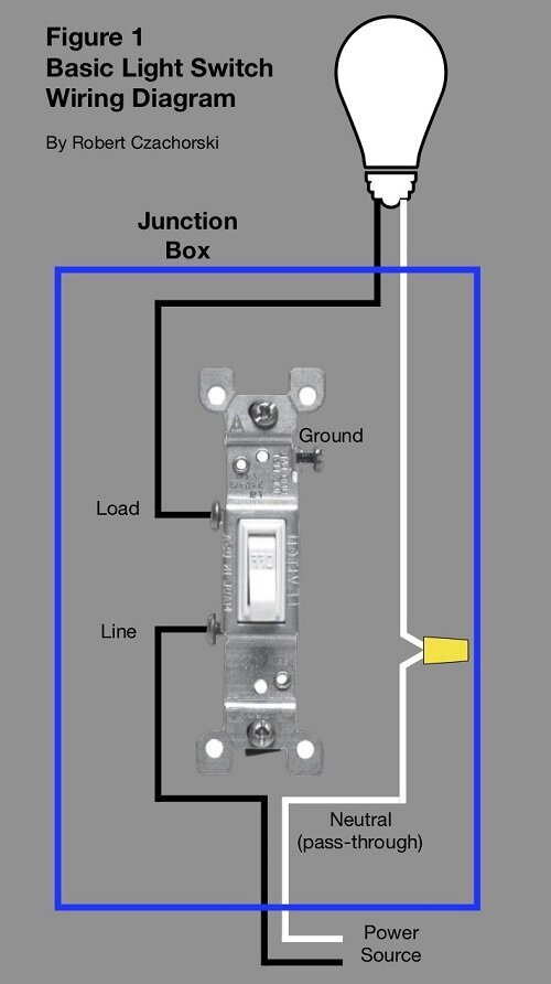
Basic Switch Wiring Diagram
Figure 1 below shows the wiring diagram for a basic switch. For a device controlled by a switch, like a light fixture, the switch breaks the black (hot) wire. This is shown in the figure. When the switch is on, the black wire is connected through the switch. And when the switch is off, the black wire is not connected. All you are doing when you flip the switch is toggling the connection of the black wire. That is what turns the light on and off. Pretty simple so far, right?
The white wire (neutral) must connect to the light fixture to complete the circuit. The white wire will not connect to the switch in this case. It usually passes through the switch junction box and then connects directly to the light. This is the basic way that a switch works.
Basic Switch Wiring Diagram
Smart Switch Wiring

GE Smart Switch Wiring Connectors on the Back
A smart switch is a key element of a smart home. Before getting starting with wiring, be sure to familiarize yourself with the introduction to wiring and basic (non-smart) switch wiring.
Smart switches work exactly like the basic light switch – the black wire goes through the switch and is toggled on or off by the switch. The white wire goes to the light. But the only difference is that the smart switch itself also needs power to operate.
Whereas a basic light switch does not (it needs no power to toggle the black wire open or closed). The white wire must also be connected to the smart switch, so that it too can have power. The white wire usually passes though the switch junction box, as shown in the diagram above.
Need for Neutral (white) Wire
Some home wiring may not have the white (neutral) wire in the switch junction box. A neutral wire is needed to power many smart switches, and without one, your options will be limited. There are options, however, and you can find our best picks for no-neutral switches here.
Step-By-Step Instructions for Wiring a Smart Switch
Once you understand these basics, the instructions that come with the switch and the connections
required will make more sense. Figure 2 below shows the wiring diagram for a single smart
switch.

Single Smart Switch Wiring Diagram
Here are the step-by-step wiring instructions:
Power off. Always be sure to turn the power off at the breaker before starting any wiring work.
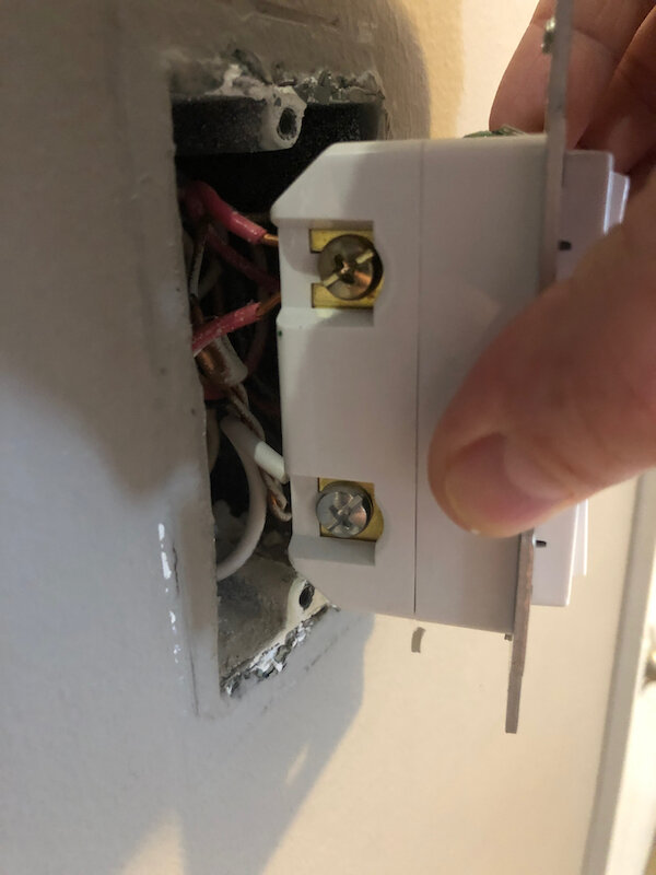
Connect the black wires (line and load) to the terminals on the left side of the switch. The black wire that goes to the light connects to the top terminal (load) and the black wire from the circuit box connects to the bottom terminal (line). These are the same black-wire connections that you have on your old switch. So just transfer them over in-kind.
Connect the white wire (neutral). For the white wire, it is necessary to splice off the existing white wire inside the box (extra wire conveniently comes with the smart switches). Connect the spliced white wire to the bottom right terminal (neutral). This wire is necessary to provide power to the switch itself.
Connect the ground wire to the ground terminal. Note that the terminal in the top right of the switch labeled “traveler” has a piece of tape over it. It is for three-way switch wiring, which is covered below. It is not needed for wiring a single switch.
That’s it. A lot of explanation for a very simple wiring job that involves connecting a few wires to the proper nodes. Below are some photos of the wiring of one of my single smart switches.

Wiring on one side of a single smart switches. Note that the black wires connect to
the line and load terminals just like a basic switch that is being replaced.
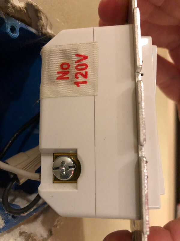
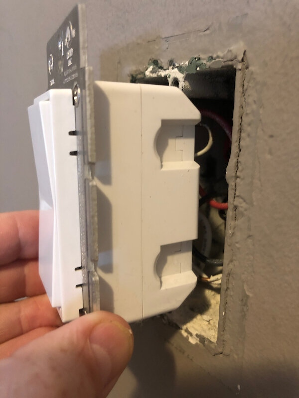
Wiring on the other side of the single smart switch. Note that the white wire
connects to the neutral terminal so that the switch can be powered and connect to
your smart network. The white wire is spliced from the existing white wires that
pass through the switch junction box.
Three Way Smart Switch Wiring
Before getting starting wiring a smart switch, be sure to familiarize yourself with the introduction to wiring and basic (non-smart) switch wiring. It would also be beneficial if you have already wired a single smart switch. If you have not, review wiring a smart switch above for a good overview.
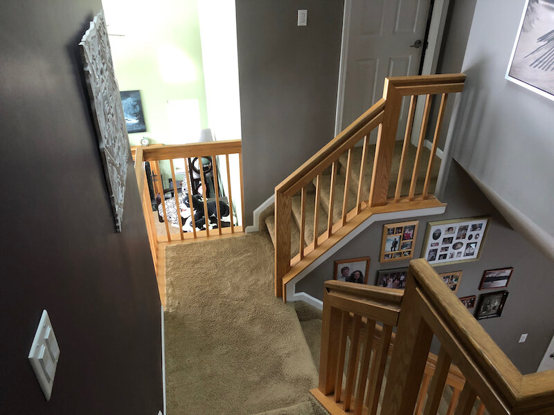
Three of the switches in a five-way switch in our stairs.
Three-Way Switch Basics
We all have three-way switches somewhere in our homes. These are switches where one light can be controlled by two switches. Replacing an existing three-way switch with a smart switch may seem complicated. But the process is actually pretty simple and logical and makes use of existing wires in most junction boxes.
The Wires In a Regular Three-Way Switch
First, let’s start with a regular (non-smart) three-way switch. The main difference between a basic single switch and a three-way switch is that the three-way switch has an extra red wire (traveler). This extra wire provides another connection between the switches so that either switch is capable of sending power to the light.
How a Smart Three-Way Switch Works
In a smart three-way switch, only one of the switches sends power to the light (the primary switch). The other switch (add-on switch) communicates with the primary switch to tell the primary switch to turn on or off. In fact, the add-on switch does not even have terminals for the black wires.
This may seem strange at first, but it should make sense. In a smart home, only one switch needs to be controllable by the smart network. The other add-on switch is just there for us humans to be able to manually toggle the switch.
How to Wire a Smart Three-Way Switch
With this basic understanding of how the smart three-way switch works, wiring a smart three-way switch should make more sense. The GE smart three-way switch comes with detailed instructions and a wiring diagram that is accurate. But it suffers a bit from too much information, so I am going to simplify the process and walk through the step-by-step wiring requirements for each switch. I will also cover why each is step is needed. Figure 3 below shows the wiring diagram for a three-way smart switch.

Three Way Smart Switch Wiring Diagram
Try not to be overwhelmed by the diagram. Sticking with the theme of this post, it is not as hard as you think! There are only a few connections to make in each junction box, and you are already familiar with most of them if you have already done a single smart switch. I will walk you through the step-by-step instructions for each switch.
Wiring the Primary Switch
The primary switch in the left Junction Box in Figure 3 powers the light and has the smart controller in it. It does not matter which switch you choose as the primary switch. But the primary switch will have the blue indicator light on it, so that might be a deciding factor for placement. Wiring the primary switch starts off exactly like the single smart switch, with one additional step for the traveler wire. Here are the step-by-step instructions for wiring the primary switch:
Power off. Always be sure to turn the power off at the breaker before starting any wiring work.
Connect the black wires (line and load) to the terminals on the left side of the switch. The black wire that goes to the light connects to the top terminal (load), and the black wire from the circuit box connects to the bottom terminal (line). These are the same black-wire connections that you have on your old switch. So just transfer them over in-kind.
Connect the white wire (neutral). For the white wire, it is necessary to splice off the existing white wire inside the box (extra wire conveniently comes with the smart switches). Connect the spliced white wire to the bottom right terminal of the primary switch (neutral). This wire is necessary to provide power to the switch itself.
Connect the red wire (traveler) from your existing three-way switch to the upper right terminal of the primary switch. This provides a connection between the primary and add-on switches.
Connect the ground wire to the ground terminal.
Wiring the Add-On Switch
The add-on switch in the right Junction Box in Figure 3 is a little different. It starts off with a couple of familiar steps with the white wire and traveler, but has one new step with the black wires (step 3). Here are the step-by-step instruction for wiring the add-on switch:
Connect the white wire (neutral). For the white wire, it is necessary to splice off the existing white wire inside the box (extra wire conveniently comes with the smart switches). Connect the spliced white wire to the bottom left terminal of the add-on switch (neutral). This wire is necessary to provide power to the switch itself.
Connect the red wire (traveler) to the upper left terminal of the add-on switch. This provides a connection between the primary and add-on switches.
Twist the black wires together. Twist the black line and load lines together that connected to your old switch. This might seem a little strange at first. It was for me. But if you study the diagram in Figure 3, you will see that what you are actually doing by twisting these wires together is completing the circuit and delivering power to the primary switch. Recall that only the primary switch needs to break the black line in a smart three-way switch. So by twisting the black wires together, you are creating that single black line going to the primary switch.
Connect the ground wire to the ground terminal.
Wiring on one-side of a three-way smart switch. This switch has two red traveler wires connected, because it is in the middle of a chain of a five-way switch.
Notice how this add-on switch has no terminals for the black line and load wires that
connected to your old switch. The black wires don’t connect to the add-on switch. They get twisted together to complete the circuit and send power to the primary
switch.
That’s it. A little more complicated than a single switch, but very logical with only a few connections to make in each switch, and most of them are just transferred in kind from your existing switches.
Four Way Smart Switch Wiring (or more)
Before getting starting wiring a smart switch, be sure to familiarize yourself with the introduction to wiring and basic (non-smart) switch wiring. It would also be beneficial if you have already wired a single smart switch and a three-way smart switch. If you have not, review wiring a smart switch and wiring a three-way smart switch for good overviews.
Four Way Smart Switch Wiring
Once you have grasped the concept of installing a three-way smart switch, adding more switches to control the light is easy. It is just a matter of adding more add-on switches to the circuit. It really is just that easy! There is one new item to be aware of with primary switch placement noted below. Here are the steps for wiring a four-way (or more) smart switch:
Power off. Always be sure to turn the power off at the breaker before starting any wiring work.
Primary switch – Wire the primary switch following the exact same steps for a three-way switch. They key thing here is to place the primary switch at one end of the chair (not in the middle). With three or more switches in the circuit, there will be two switches (one on each end of the chain) that only have one red traveler wire going to them. The switch (or switches) in the middle of the chain will have two-red traveler wires going to them. These connect to each switch on either side in the chain. Place the primary switch in one of the two junction boxes that has a single red traveler wire connecting to the existing switch.
Add-on switches – For each add-on switch, follow the exact same steps outlined above for the three-way switch. For the add-on switch in the middle of the chain, just connect both red wires to the traveler terminal.
Four-way or more switches can be wired by just adding more add-on switches to the circuit. That’s it! Once you have wired a three-way smart switch, doing a four-way smart switch (or more) is not that difficult, and build on what you have already learned.